webg
Fundamentals of 3D Space
To create a 3D scene, choose the positions and orientations of objects and the position of the camera that views them. This chapter introduces the coordinate concepts used throughout later chapters by placing a cube, rotating it, and giving it a parent.
Start by understanding which parts of the display change when you change a value. Chapter 41 explains matrix layouts and projection equations as part of the rendering internals.
How to read this chapter
Prerequisites
You need to know JavaScript arrays and how positive and negative numbers represent positions. The snippets illustrate individual operations on a scene; Chapter 04 shows how to put them into a complete application. You can also run book/examples/03_01.html to explore the ideas before writing your own code.
What to read first
Read about the three coordinate axes, positions and rotations, local and world coordinates, the camera and field of view, and surface normals and UVs, in that order.
What to read when you need it
Refer to the celestial-body and joint examples in the second half when moving groups of objects. Chapter 38 covers vertex order, normals, and UVs when building faces by hand; Chapter 41 explains matrices, projections, and quaternion calculation rules.
What you will learn
You will be able to place an object at a specified position, change its orientation, and move a group through parent-child relationships. You will also be able to explain how camera distance and field of view affect the image.
Learn the three coordinate axes
A position is represented by three numbers: X, Y, and Z. When viewing the origin from the standard viewpoint, positive X points right and positive Y points up. The camera looks along its local -Z axis. Rotating an object or camera also changes its direction on the screen, so begin by checking an object near the origin.
World coordinates use a right-handed EUS (East-Up-South) system: east is +X, up is +Y, and south is +Z. Each object and camera has its own local coordinates within this shared reference system.
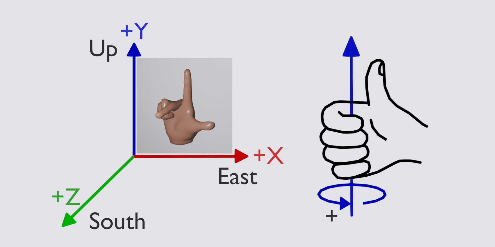
The position [0, 0, 0] is the origin. [2, 0, 0] is two units along X, while [0, 3, 0] is three units along Y. In the physics and physical-scale texture examples in this book, one unit of length corresponds to one meter.
The following fragment adds a Node for placement to an existing Space. A Node has a position and orientation; Chapter 04 adds the visible shape.
const box = space.addNode(null, "box");
box.setPosition(2.0, 1.0, 0.0);
The parent is null, so the position is relative to the scene origin. Changing Y to 2 moves the center of the box up by one unit. The center and bottom face of an object are at different positions. To align the bottom of a box of height 2 with Y=0, place its center at Y=1.
Change an object’s orientation
Specify rotations with yaw for turning left or right, pitch for tilting up or down, and roll for tilting sideways. Angles passed to setAttitude(yaw, pitch, roll) are in degrees.
| Parameter | Rotation axis | Motion to check |
|---|---|---|
yaw |
Y axis | Turn left or right |
pitch |
X axis | Tilt up or down |
roll |
Z axis | Tilt sideways |
box.setAttitude(30.0, 0.0, 0.0);
box.rotateY(10.0);
setAttitude() sets the orientation; rotateY() adds a rotation to the current orientation. In this example, the object first turns 30 degrees around Y and then rotates another 10 degrees. For continuous rotation, multiply the per-second angle by elapsed time, as in Chapters 04 and 05.
The positive rotation direction follows the right-hand rule: point your right thumb along the positive axis, and the direction in which your fingers curl is positive. Viewed from the positive side of the axis toward the origin, positive rotation is counterclockwise. Specify rotations around multiple axes in the order yaw(Y) → pitch(X) → roll(Z). Internally, orientation is stored as a quaternion with four components and converted to a matrix for rendering. Chapter 41 explains the calculation.
Use local and world coordinates
World coordinates are positions relative to the scene origin. Local coordinates are positions relative to a parent Node. Moving a parent also moves its children. This makes it possible to place a vehicle and its wheels, an arm and its hand, or a model and its attachments as a group.
const vehicle = space.addNode(null, "vehicle");
vehicle.setPosition(4.0, 0.0, 0.0);

const lamp = space.addNode(vehicle, "lamp");
lamp.setPosition(0.0, 2.0, 0.0);
With the parent at its default rotation and scale, the lamp’s world position is [4, 2, 0]. Moving the vehicle one unit along X also moves the lamp one unit along X, while the lamp’s local position [0, 2, 0] stays the same.
When a parent rotates, the child’s local position rotates with it. For example, an attachment on the right side of a vehicle stays on that side after the vehicle turns. When reading values passed to setPosition(), check the Node’s parent.
Set the view with camera distance and field of view
A camera has a position and orientation from which it views objects. Chapter 04 uses an orbit camera that moves around a target. Move the camera closer when an object looks too small, and farther away when it looks too large.
The field of view (FOV) is the angular extent of the camera’s view. In WebgApp, viewAngle specifies the angle in degrees along the shorter canvas dimension: vertical in landscape orientation and horizontal in portrait orientation. Chapter 06 explains how this is converted to the vertical FOV used by the projection matrix. At the same camera distance, a wider FOV includes more of the scene and makes objects look smaller; a narrower FOV shows a smaller area at a larger scale.
With perspective projection, nearby objects appear larger and distant objects appear smaller. Adjusting camera distance separately from field of view makes it easier to compose a scene. WebgApp uses projectionNear and projectionFar to define the rendered depth range. Chapter 06 explains camera controls and settings; Chapter 41 covers projection equations and depth precision.
Describe surfaces with normals and UVs
The vertices of a shape describe positions on its surface. A normal describes the direction a surface faces and is used to calculate its response to light. A flat face uses the same normal at each vertex. A curved surface uses normals that vary from vertex to vertex; interpolating those normals across its triangles produces smooth shading.
UVs are two values that describe a position in an image. Adding UVs to vertices determines which part of an image is mapped to each part of the surface. A full image usually maps to the range from 0 to 1; repeating patterns use values beyond that range. Chapter 29 covers patterns mapped to physical dimensions.
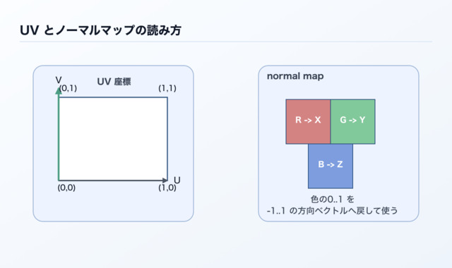
A normal map specifies small changes in surface orientation in an image. It adds fine-grained shading without increasing the vertex count. Shapes created with Primitive already include the vertices, normals, and UVs needed for rendering, so you can use those results directly when getting started. When creating custom faces, Chapter 38 explains vertex order, face orientation, normals, and UV mapping.
Extend parent-child hierarchies to celestial bodies and joints
When first using Node or bones, one question often causes confusion: “Which coordinate system defines this position or rotation?”
In webg, both Node objects and bones form hierarchies from parent to child.
Each element has a position and orientation relative to its parent. These are its local coordinates.
If code is written before this relationship is clear, rotating Earth may unexpectedly move the Sun along with the Moon.
Once parent-child relationships and local coordinates are clear, Node placement, camera rigs, bone hierarchies, and animation all follow the same idea.
Understand the hierarchy through celestial bodies
The relationship between the Sun, Earth, and Moon is an intuitive way to understand a hierarchy. The Sun rotates on its axis; Earth orbits the Sun while rotating on its own axis; and the Moon orbits Earth while rotating on its own axis. The Moon’s position is the result of combining Earth’s world position with the Moon’s local position relative to Earth.
With Node, the parent-child structure looks like this:
sun (solar-system reference)
├── sunBody (Sun appearance and rotation)
└── earthOrbit (Earth's orbit)
    └── earth (Earth's position)
        ├── earthBody (Earth appearance and rotation)
        └── moonOrbit (Moon's orbit)
            └── moon (Moon appearance and rotation)
Setting earth’s local position to [3.6, 0, 0] means that Earth is 3.6 units along X relative to its parent, earthOrbit.
Rotating earthOrbit makes its child, earth, appear to orbit in a circle with a radius of 3.6.
The Moon’s world matrix is composed as follows:
sunWorld = sunLocal
earthOrbitWorld = sunWorld * earthOrbitLocal
earthWorld = earthOrbitWorld * earthLocal
moonOrbitWorld = earthWorld * moonOrbitLocal
moonWorld = moonOrbitWorld * moonLocal
With column vectors, transformations on the right act first. When computing moonWorld * v, moonLocal first transforms the Moon’s local geometry v; then the Moon’s orbit around Earth, Earth’s placement, and the orientation of the whole solar system are applied in sequence.
It helps to think of each child as building on the transformed result of its parent.
Separate each orbit pivot from the body that rotates on its own axis. Attach the Sun’s Shape to sunBody and Earth’s Shape to earthBody. Place moonOrbit as a sibling of the rotating earthBody, so changing Earth’s rotation speed leaves the Moon’s orbit independent. The following example shows these Nodes and their updates:
const sun = app.space.addNode(null, "sun");
const sunBody = app.space.addNode(sun, "sunBody");

const earthOrbit = app.space.addNode(sun, "earthOrbit");
const earth = app.space.addNode(earthOrbit, "earth");
earth.setPosition(3.6, 0.0, 0.0);
const earthBody = app.space.addNode(earth, "earthBody");

const moonOrbit = app.space.addNode(earth, "moonOrbit");
const moon = app.space.addNode(moonOrbit, "moon");
moon.setPosition(1.3, 0.0, 0.0);

app.start({
  // Advance orbit pivots and rotating bodies independently using elapsed seconds
  onUpdate({ deltaSec }) {
    sunBody.rotateY(12.0 * deltaSec);    // Sun's rotation
    earthOrbit.rotateY(24.0 * deltaSec); // Earth's orbit
    earthBody.rotateY(72.0 * deltaSec);  // Earth's rotation
    moonOrbit.rotateY(55.0 * deltaSec);  // Moon's orbit
    moon.rotateY(48.0 * deltaSec);       // Moon's rotation
  }
});
Rotating earthOrbit affects Earth and the Moon beneath it, while the Sun itself keeps its position and orientation. Moving sun affects Earth and the Moon together. This is the basic rule of a hierarchy: a parent’s transform propagates to its children, while a child’s transform does not propagate back to its parent.
Apply the same idea to human joints and coordinate propagation
The same principle applies to human joints. Moving the waist also moves the shoulders, arms, and hands. Rotating the shoulder moves the upper arm, forearm, and hand. Bending the elbow moves the forearm and hand, while the shoulder and waist remain the parent-side references. This is exactly how a parent-child hierarchy works.
A simplified right arm has this hierarchy:
waist
└── torso
    └── shoulder
        └── upperArm
            └── foreArm
                └── hand
Define the hand’s position relative to its parent, for example by specifying how far it is from the end of the forearm. The waist’s movement, a twist of the torso, shoulder rotation, and elbow flexion then propagate naturally to the hand.
const waist = app.space.addNode(null, "waist");
waist.setPosition(0.0, 0.0, 0.0);

const torso = app.space.addNode(waist, "torso");
torso.setPosition(0.0, 1.8, 0.0);

const shoulder = app.space.addNode(torso, "shoulder");
shoulder.setPosition(0.9, 0.9, 0.0);

const upperArm = app.space.addNode(shoulder, "upperArm");
upperArm.setPosition(1.2, 0.0, 0.0);

const foreArm = app.space.addNode(upperArm, "foreArm");
foreArm.setPosition(1.1, 0.0, 0.0);

const hand = app.space.addNode(foreArm, "hand");
hand.setPosition(0.6, 0.0, 0.0);
Calling shoulder.rotateZ(...) moves the upper arm, forearm, and hand together along an arc.
Calling foreArm.rotateZ(...) adds a bend from the elbow onward.
This happens because the hand’s world matrix is the product of every local matrix from the waist to the hand.
handWorld
  = waistWorld
  * torsoLocal
  * shoulderLocal
  * upperArmLocal
  * foreArmLocal
  * handLocal
With this model in mind, it is easier to diagnose a distorted result: is the hand’s local value wrong, is the shoulder rotation larger than expected, or is the composed result including the waist orientation the cause?
Coordinate transforms in a bone hierarchy
Bones may look like a special mechanism, but they follow the same hierarchy as Node objects.
Bones used for skinning keep each child’s position and orientation in local coordinates relative to its parent bone, then inherit the parent’s transform to create a world pose.
const skeleton = new Skeleton();

const waistBone = skeleton.addBone(null, "waistBone");
const spineBone = skeleton.addBone(waistBone, "spineBone");
const shoulderBone = skeleton.addBone(spineBone, "shoulderBone");
const upperArmBone = skeleton.addBone(shoulderBone, "upperArmBone");
const foreArmBone = skeleton.addBone(upperArmBone, "foreArmBone");
const handBone = skeleton.addBone(foreArmBone, "handBone");

waistBone.setRestPosition(0.0, 0.0, 0.0);
spineBone.setRestPosition(0.0, 1.2, 0.0);
shoulderBone.setRestPosition(0.9, 0.8, 0.0);
upperArmBone.setRestPosition(1.1, 0.0, 0.0);
foreArmBone.setRestPosition(1.0, 0.0, 0.0);
handBone.setRestPosition(0.6, 0.0, 0.0);
Bone hierarchies combine with per-vertex weights to deform a mesh. They extend the parent-child coordinate model used to place Nodes to shape deformation. The underlying rule is the same: a parent’s rotation propagates to its children, and the world pose is composed from the parent’s transform and the child’s local transform. Chapter 40 explains how inverse bind matrices and vertex weights are added to this hierarchy so a mesh bends with its joints.
Points to check when reading a hierarchy
When reading code that uses a parent-child hierarchy, check these three things first:
- Does
setPosition()define a distance relative to the parent Node or bone? - Is the node being rotated the visible object or a pivot for an orbit or joint?
- Is the value you need in local coordinates, or is it a world coordinate obtained with a method such as
getWorldPosition()?
Keeping these distinctions in mind also helps when reading webg samples and core code.
For example, the WebgApp camera uses the hierarchy cameraRig -> cameraRod -> eye to orbit, while skinning propagates poses from the root bone to its children.
The appearance differs, but the coordinate-transform mechanism is shared.
To explore the concepts in this chapter, run book/examples/03_01.html.
It places the Sun, Earth, and Moon on the left and a waist, shoulder, arm, and hand on the right, so you can check the same parent-to-child transform rule with two subjects.
For mesh deformation using a bone hierarchy, see book/examples/40_01.html and book/examples/40_02.html from Chapter 40.
Summary
When setting a position, check its coordinate reference. When setting a rotation, check the axis and angle. When creating a parent-child hierarchy, check the position relative to the parent. Adjust camera distance and field of view to show the same scene with different compositions.
Chapter 04 uses these conventions to display a cube. Refer to Chapter 38 when building faces yourself and Chapter 41 when studying transform calculations in detail.